

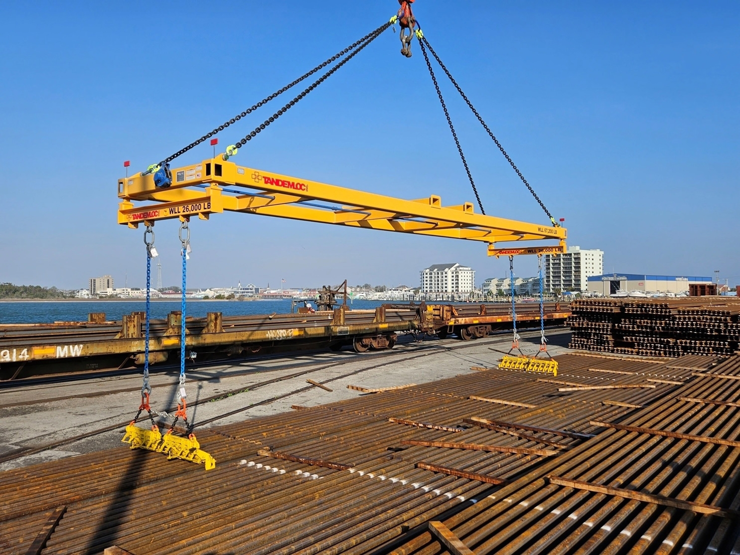

Lifting something heavy looks simple from the outside: attach a cable, engage a crane, raise the load. The engineering underneath that simplicity is considerably more demanding, particularly once a load is long, unevenly weighted, or rigid enough that it cannot bend to accommodate an awkward lift point. The equipment and geometry chosen for that lift are not incidental details. They determine whether the load rises evenly or twists, whether the rigging holds or fails, and whether the people working nearby are in danger.
Why a Single Point Is Rarely Enough
The most intuitive way to lift something is from its center, using one attachment point directly above its balance point. That approach works acceptably for compact, evenly weighted objects. It breaks down quickly for anything long, such as a length of pipe, a steel beam, or a shipping container, because a single lift point forces the entire load to hang from one location while the rest of the object extends outward with nothing supporting it directly.
Long loads lifted from a single point tend to sag, tilt, or swing unpredictably, since the object’s own weight is pulling downward along its full length while only one point resists that pull. The farther a section sits from the lift point, the more leverage it exerts against the rigging, which is why single-point lifting on an elongated load is both mechanically inefficient and considerably less stable.
What Multiple Attachment Points Change
Distributing a lift across two or more points along a load’s length changes the mechanics substantially. Instead of one location bearing the full weight and resisting all the leverage generated by the rest of the object, the load is shared, and each attachment point only has to resist the portion of weight and leverage nearest to it.
This is the basic principle behind spreader beams and lift beams, rigid components placed between a crane hook and a load’s multiple attachment points specifically to hold those points apart at a fixed, engineered distance. Rather than slings converging toward a single hook and pulling inward on the load as they rise, a spreader beam keeps the lift points spread and the slings running vertically, which removes a substantial source of instability.
The Angle Problem Slings Create on Their Own
Without a spreader beam, slings running from multiple points on a load up to a single hook form an angle relative to vertical, and that angle matters more than it might appear to. As the angle between a sling and vertical increases, the tension the sling has to bear to support the same vertical weight increases as well, sometimes dramatically. A sling angled sharply inward toward a converging hook can end up under considerably more tension than one hanging straight down carrying the identical share of the load.
This is a purely geometric consequence, not a matter of sling quality or rigging skill. It means that lifting arrangements which look reasonable at a glance can quietly be putting far more stress on the rigging than the visible weight of the load would suggest. Keeping slings vertical, which is exactly what a spreader beam is designed to do, removes that hidden multiplication of tension entirely.
Compression, Tension, and Why the Beam Itself Has to Be Engineered
A spreader beam does not merely hold two points apart passively. It is a structural member placed under its own combination of forces, primarily compression along its length as it resists being squeezed together by the inward pull of the slings beneath it, and bending stress generated by the load hanging from its ends. An undersized or improperly designed beam can buckle or bend under those forces even if the slings themselves are rated well beyond the weight being lifted.
This is why lifting beams are not generic steel bars but engineered components, sized and rated for specific load capacities and specific distances between attachment points. A beam adequate for a shorter span carrying a given weight is not automatically adequate for a longer span carrying the same weight, because the bending forces involved increase with distance even when the total weight does not change.
Where Long Loads Show Up Beyond Construction
The same lifting problem appears constantly outside of construction sites. Intermodal shipping containers, for instance, are long, rigid, and typically lifted using dedicated attachment points built into their corner castings, connected to a crane through a rigid frame rather than simple slings, for precisely the reasons described above. Manufacturing facilities moving long coils, pipe sections, or fabricated steel components face an identical set of physical constraints regardless of industry.
Tandemloc Inc. designs and manufactures spreader beams, lift beams, and container-handling equipment built around these load-distribution principles, engineered domestically and rated for specific capacities and spans rather than sold as generic lifting hardware. The underlying physics does not change from one industry to the next; only the shape and scale of the load does.
Certification as a Reflection of Consistency
Equipment used in lifting is generally expected to meet recognized quality and safety standards, and manufacturers producing this kind of equipment commonly operate under formal quality management certifications covering design, testing, and production consistency. That kind of certification exists because a beam’s rated capacity is only meaningful if the beam reliably performs as rated across every unit produced, not just the one that happened to be tested.
Proof testing, in particular, is standard practice for lifting equipment: applying a load beyond the rated working capacity to a sample or unit before it enters service, confirming the margin between rated and actual failure point holds as designed. That testing step exists because the consequences of a miscalculated margin in lifting equipment are considerably more severe than in most other manufactured goods.
What the Geometry Is Actually Protecting
None of this complexity is visible in the finished lift. From the ground, a well-executed rigging job with a spreader beam and evenly loaded points looks unremarkable, which is precisely the point. The visible calm of a stable, level lift is the result of geometry and load distribution having been worked out in advance, not a matter of the load simply being light enough to behave.
Recognizing that the math sits underneath every successful lift is a useful reminder for anyone who works around heavy loads, even without doing the engineering personally. The margin between a routine lift and a serious failure is frequently a matter of a few degrees of sling angle or a few inches of beam span, details invisible to anyone not specifically looking for them.